Automatic Aquarium
📅 May 2026About This Project
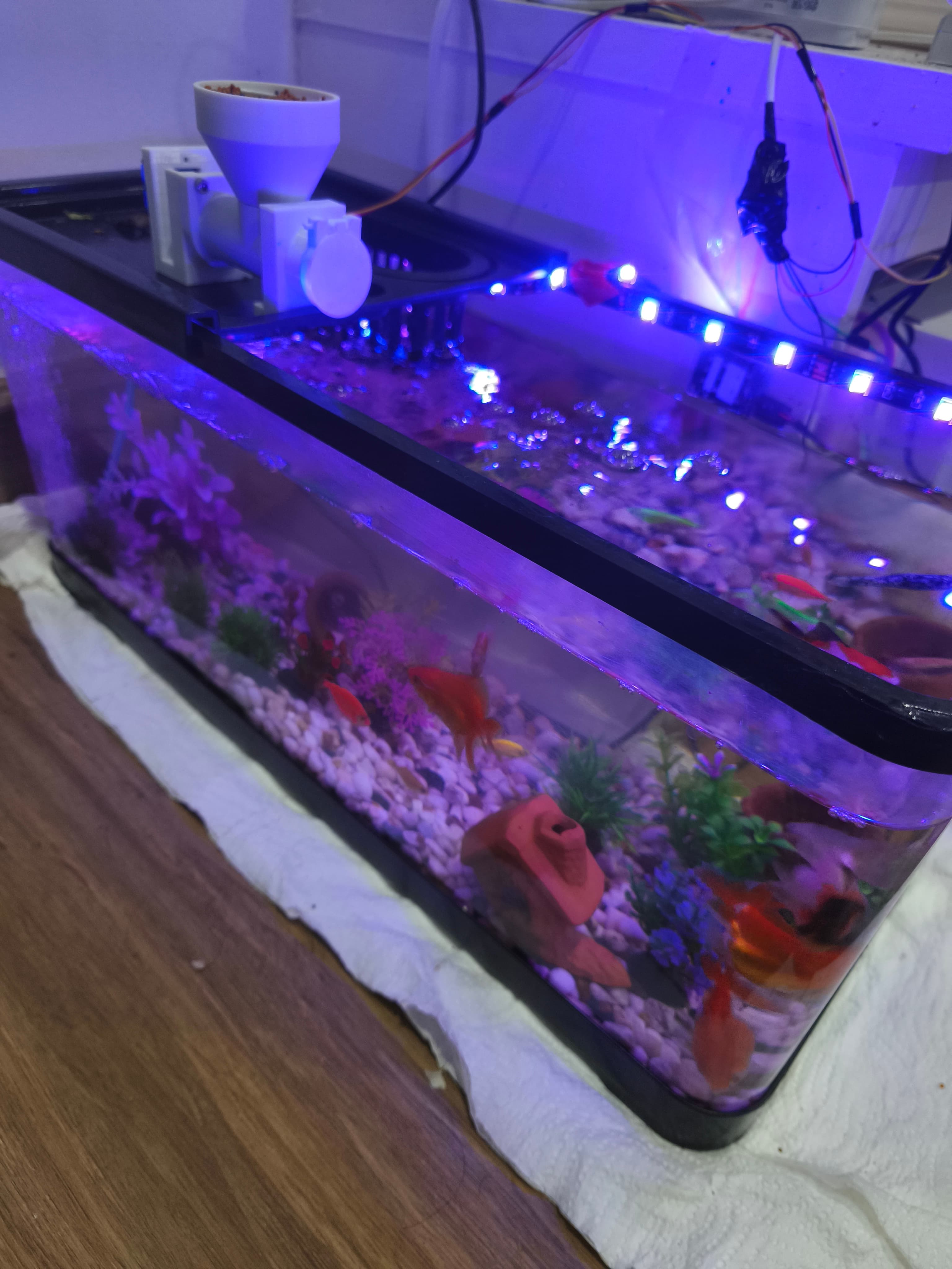
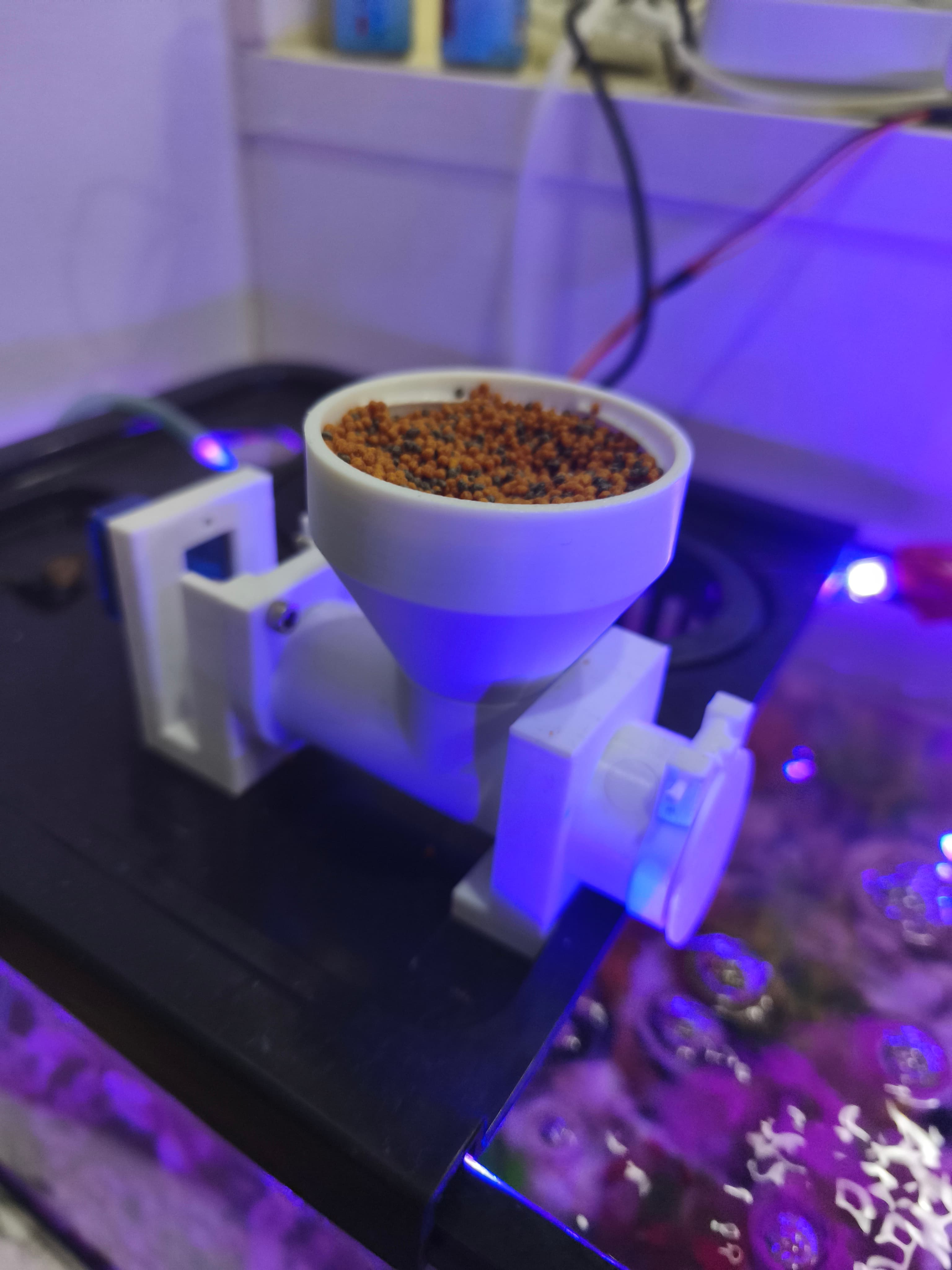
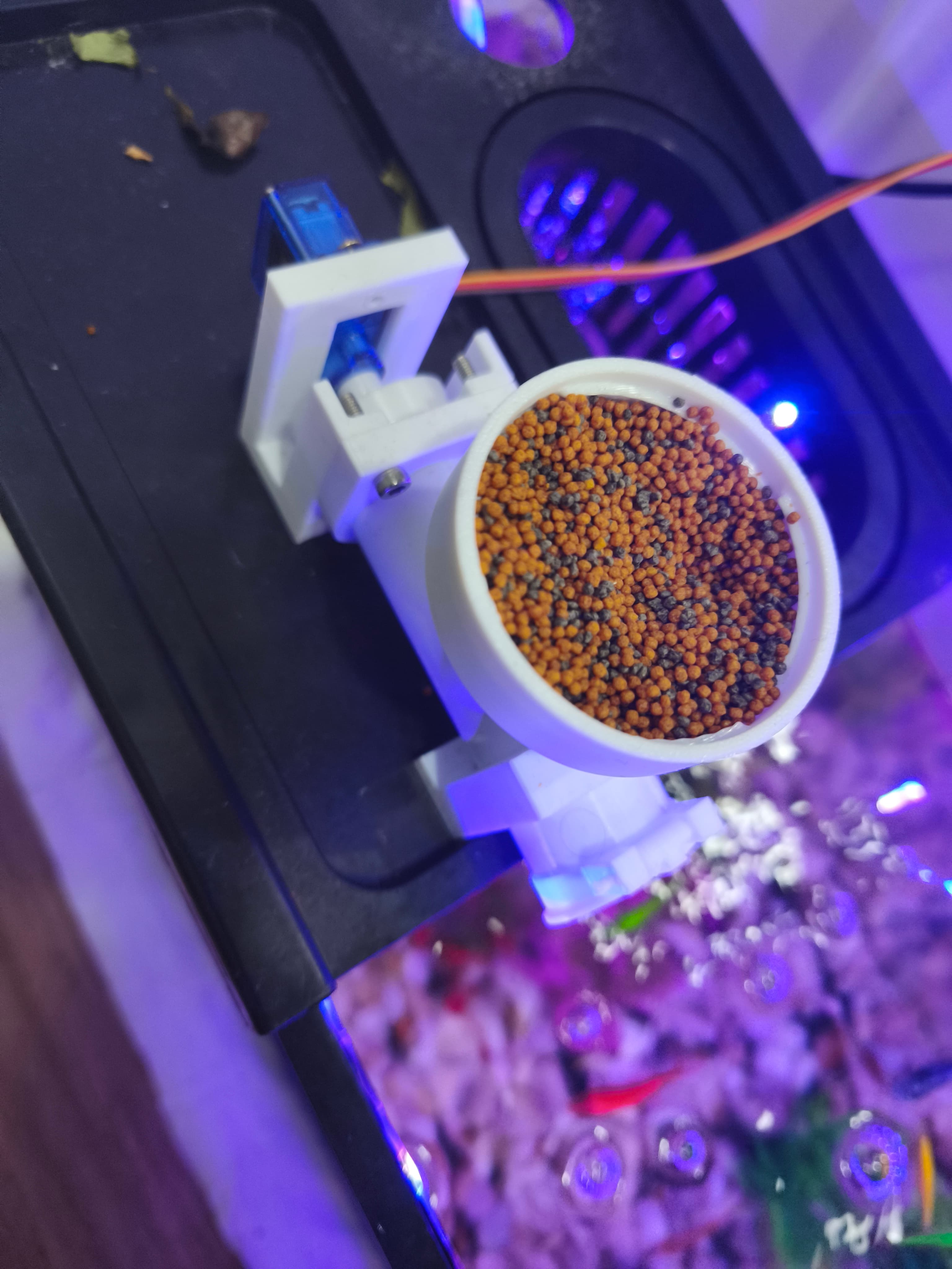
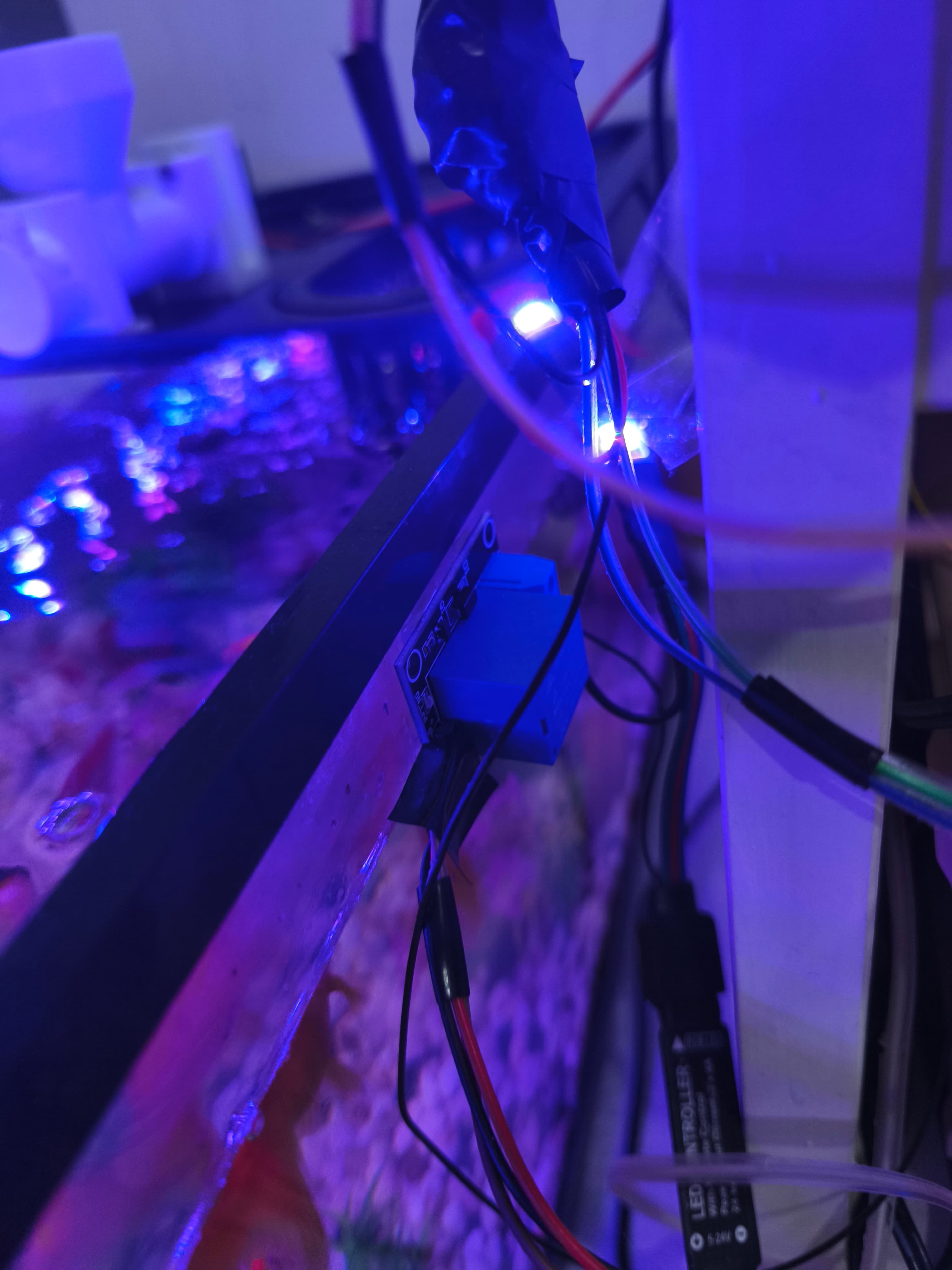
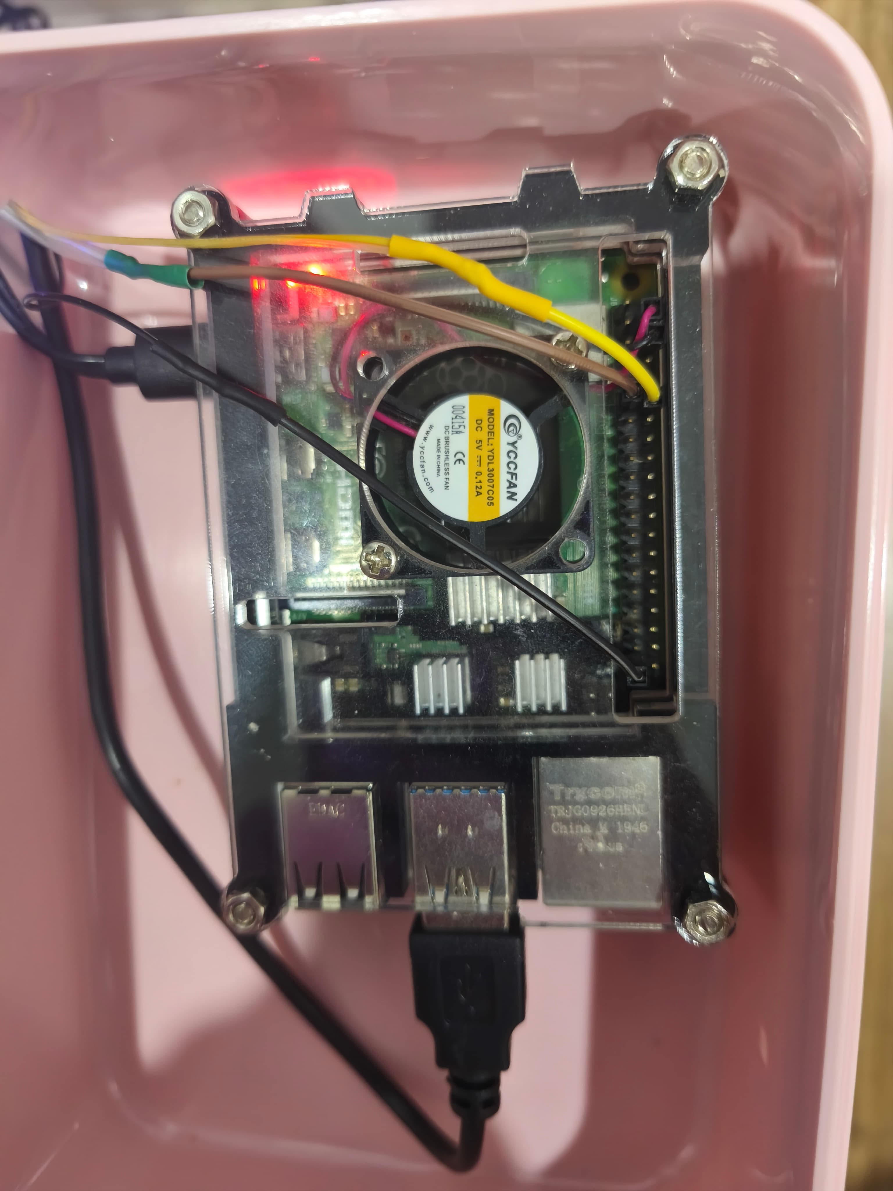
Welcome to my automatic aquarium project ### Parts: - Aquarium - Automatic feeder (Entirely 3D printed) - 3D printer to print parts - Filament (I used PLA) - 1x SG90 360° continuous servo - 1x 1 channel 5V Relay - 1x USB cable (I used an old phone cable that was no longer working) - DuPont cables to connect the electronics to the Raspberry Pi - Led light or any 5v light (I used a 2M strip) - Raspberry Pi (I used a Raspberry Pi 4 8Gb) <img src="https://iuawmxvsbadbzemjnmix.supabase.co/storage/v1/object/public/portfolio/uploads/1780073631041-Screenshot-2026-05-29-174937.png" alt="image" /> ## Aquarium <img src="https://iuawmxvsbadbzemjnmix.supabase.co/storage/v1/object/public/portfolio/uploads/1780058334020-Aquarium.webp" alt="image" width="50%" /> For the aquarium you can use whatever you want. ## Automatic feeder For the feeder I found a nice project online that I customized a little bit to fit my needs. **Why i choosed this type?** I saw a few feeders online but for me this was easy to make and doesn't limitate me for the food capacity (Do you need more food capacity? Print a bigger Hopper). **NOTE** I saw that with this feeder and my small aquarium the food inside the feeder can easily last 2 weeks. It obviusly depends on how many times a day you feed them and how much food the feeder push out. ## Those are the 3d parts: [📎 Auger V3.stl](https://iuawmxvsbadbzemjnmix.supabase.co/storage/v1/object/public/portfolio/uploads/files/1780054482109-Auger-V3.stl) <img src="https://iuawmxvsbadbzemjnmix.supabase.co/storage/v1/object/public/portfolio/uploads/1780058463701-Auger-V3.png" alt="image" width="50%" /> </br> </br> </br> [📎 auger_tubev2.stl](https://iuawmxvsbadbzemjnmix.supabase.co/storage/v1/object/public/portfolio/uploads/files/1780054492629-auger_tubev2.stl) <img src="https://iuawmxvsbadbzemjnmix.supabase.co/storage/v1/object/public/portfolio/uploads/1780058547605-Auger_tubev2.png" alt="image" width="50%" /> </br> </br> </br> [📎 Hopper.stl](https://iuawmxvsbadbzemjnmix.supabase.co/storage/v1/object/public/portfolio/uploads/files/1780054498857-Hopper.stl) <img src="https://iuawmxvsbadbzemjnmix.supabase.co/storage/v1/object/public/portfolio/uploads/1780058596180-Hopper.png" alt="image" width="50%" /> </br> </br> </br> [📎 Motor bracket V3.stl](https://iuawmxvsbadbzemjnmix.supabase.co/storage/v1/object/public/portfolio/uploads/files/1780054506207-Motor-bracket-V3.stl) <img src="https://iuawmxvsbadbzemjnmix.supabase.co/storage/v1/object/public/portfolio/uploads/1780058659813-Motor-bracket-V3.png" alt="image" width="50%" /> </br> </br> </br> [📎 Servo connector V3.stl](https://iuawmxvsbadbzemjnmix.supabase.co/storage/v1/object/public/portfolio/uploads/files/1780054514743-Servo-connector-V3.stl) <img src="https://iuawmxvsbadbzemjnmix.supabase.co/storage/v1/object/public/portfolio/uploads/1780058715043-Servo-connector-V3.png" alt="image" width="50%" /> </br> </br> </br> [📎 Tampa da tampa V3.stl](https://iuawmxvsbadbzemjnmix.supabase.co/storage/v1/object/public/portfolio/uploads/files/1780054522224-Tampa-da-tampa-V3.stl) <img src="https://iuawmxvsbadbzemjnmix.supabase.co/storage/v1/object/public/portfolio/uploads/1780058772182-Tampa-da-tampa-V3.png" alt="image" width="50%" /> </br> </br> </br> [📎 Tampa tube V3.stl](https://iuawmxvsbadbzemjnmix.supabase.co/storage/v1/object/public/portfolio/uploads/files/1780054530692-Tampa-tube-V3.stl) <img src="https://iuawmxvsbadbzemjnmix.supabase.co/storage/v1/object/public/portfolio/uploads/1780058927158-Tampa-tube-V3.png" alt="image" width="50%" /> </br> </br> </br> [📎 tampa.stl](https://iuawmxvsbadbzemjnmix.supabase.co/storage/v1/object/public/portfolio/uploads/files/1780054538751-tampa.stl) <img src="https://iuawmxvsbadbzemjnmix.supabase.co/storage/v1/object/public/portfolio/uploads/1780058975146-tampa.png" alt="image" width="50%" /> </br> </br> </br> [📎 Tube_support.stl](https://iuawmxvsbadbzemjnmix.supabase.co/storage/v1/object/public/portfolio/uploads/files/1780054544185-Tube_support.stl) <img src="https://iuawmxvsbadbzemjnmix.supabase.co/storage/v1/object/public/portfolio/uploads/1780059034350-Tube-support.png" alt="image" width="50%" /> </br> </br> </br> ### Reference: [Reference Fish feeder](https://www.thingiverse.com/thing:736693) Electronics used: - SG90 360° continuous servo - 1 channel 5V Relay - USB cable (I used an old phone cable that was no longer working) - DuPont cables to connect the electronics to the Raspberry Pi Follow the images below as a visual reference while going through the steps: <img src="https://iuawmxvsbadbzemjnmix.supabase.co/storage/v1/object/public/portfolio/uploads/1780055197743-IMG_20260529_183939.jpg" alt="image" width="70%" /> <img src="https://iuawmxvsbadbzemjnmix.supabase.co/storage/v1/object/public/portfolio/uploads/1780055219943-IMG_20260529_183943.jpg" alt="image" width="70%" /> <img src="https://iuawmxvsbadbzemjnmix.supabase.co/storage/v1/object/public/portfolio/uploads/1780055242821-IMG_20260529_184001.jpg" alt="image" width="70%" /> <img src="https://iuawmxvsbadbzemjnmix.supabase.co/storage/v1/object/public/portfolio/uploads/1780055252743-IMG_20260529_184007.jpg" alt="image" width="70%" /> 1. Insert the 2 screws into the motor bracket without nuts — the parts grip tightly enough on their own that nuts aren't needed. 2. Place the servo into the bracket. 3. Attach the servo connector and secure it with its screw to lock all parts in position. **Known issue / planned improvement:** Sometimes when picking up the feeder by the hopper, the whole assembly comes apart and food spills. A future version will use a screwed hopper to fix this. ### Wiring the feeder Connect the servo to the Raspberry Pi using DuPont cables: - Signal → GPIO 18 (BCM numbering) - Power & Ground → External USB power source (see note below) **Why external power?** The Raspberry Pi 4 does not supply enough current through its GPIO pins to reliably drive both the servo and the relay. To solve this, cut the phone connector end off an old USB cable and use terminal strips to connect its positive wire (usually red) to the servo and relay power lines, and its negative wire (usually black) to the shared ground. Make sure to also connect the Raspberry Pi's ground to the same terminal strip so all components share a common ground. ### Testing the individual components Before running the full automation script, use the code below to test the servo and light independently: **Python** ``` from gpiozero.pins.pigpio import PiGPIOFactory # This forces the use of hardware timing factory = PiGPIOFactory() from gpiozero import OutputDevice, Servo, Device from time import sleep servo = Servo(18, min_pulse_width=0.5/1000, max_pulse_width=2.5/1000, pin_factory = factory) def light_test(): # Try False first, then True if it doesn't work relay = OutputDevice(17, active_high=False) print("Pulsing relay... listen for clicks and look for a tiny LED light on the relay board.") try: while True: relay.on() print("Signal ON") sleep(5) relay.off() print("Signal OFF") sleep(5) except KeyboardInterrupt: print("Test stopped.") def servo_test(): servo = Servo(18, min_pulse_width=1.0/1000, max_pulse_width=2.2/1000, pin_factory = factory) # Push food servo.value = -0.8 sleep(0.75) # Jitter servo.value = 0.4 sleep(0.1) servo.value = -0.4 sleep(0.1) servo.value = 0.4 sleep(0.1) servo.value = -0.4 sleep(0.1) # Push food back servo.value = 0.8 sleep(1) ``` ## Led light Cut the power cable on the RGB LED strip after the color controller (this lets you still change colors manually if you want) and connect it to the relay. Wire the cable coming from the controller into the COM port, and the cable going to the LED strip into the NC port. **Why NC instead of NO?** Using the Normally Closed port means the light stays on even if the Raspberry Pi is disconnected, which is useful as a fallback. Connect the relay's power and ground to the same external USB power source used for the servo. Connect the relay's signal cable to GPIO 17 (BCM) on the Raspberry Pi. Finally, make sure the Raspberry Pi's ground is connected to the shared terminal strip alongside the relay and servo grounds. This common ground is required for the signal communication to work correctly. ## Automation script Once everything is wired, run the script below on the Raspberry Pi to automate feeding and lighting. The configuration section at the top is the only part you should need to change. **Python** ``` from gpiozero.pins.pigpio import PiGPIOFactory # This forces the use of hardware timing factory = PiGPIOFactory() from gpiozero import OutputDevice, Servo, Device from datetime import datetime import time from time import sleep # --- CONFIGURATION --- PIN_LIGHT = 17 PIN_SERVO = 18 # --- SCHEDULE SETTINGS --- # Set your specific times here (HH, MM, SS) # Time with pc so # Turn on at 9 AM LIGHT_ON_TIME = (9, 0, 0) # Turn off at 5 PM LIGHT_OFF_TIME = (17, 0, 0) # Days to skip feeding (0=Monday, 1=Tuesday, ..., 6=Sunday) SKIP_FEEDING_DAYS = [2, 6] # e.g. [5, 6] to skip Saturday and Sunday # Execute feeding SERVO_TIMES = [ (10, 0, 0), # Feeding at 10 AM ] # Loop wait execution WAIT_TIME = 600 # Set to False if you want feeding at startup SKIP_PAST_FEEDINGS_ON_START = True # Setup GPIO 17 for Light/Device # NOTE: I use active high false as the light is connected to NC. In this way if i want to remove the PI system # It still works normally light = OutputDevice(PIN_LIGHT, active_high=False) # Setup GPIO 18 for 360 Servo # NOTE: After some tests i saw that the 0 point of my servo motor is 1.6 servo = Servo(PIN_SERVO, min_pulse_width=1.0/1000, max_pulse_width=2.2/1000, pin_factory = factory) servo.detach() # Start with the motor "off" # Variables to track the servo schedule servo_done_today = [False * len(SERVO_TIMES)] last_date = None def run_servo_sequence(): # Push food servo.value = -0.8 sleep(0.7) # Jitter servo.value = 0.4 sleep(0.1) servo.value = -0.4 sleep(0.1) servo.value = 0.4 sleep(0.1) servo.value = -0.4 sleep(0.1) # Push food back servo.value = 0.8 sleep(1) servo.detach() # Turn off signal to prevent creeping print("Servo sequence complete.") print("System Online. Monitoring time...") first_loop = True try: while True: now = datetime.now() current_time = (now.hour, now.minute, now.second) current_date = now.strftime("%Y-%m-%d") # 1. Daily Reset: Reset the servo flag at midnight if current_date != last_date: servo_done_today = [False, False, False] last_date = current_date print(f"New day detected: {current_date}. Servo schedule reset.") # --- 1. LIGHT LOGIC (Precise Start/Stop) --- # Checks if current time is between the ON tuple and OFF tuple if LIGHT_ON_TIME <= current_time < LIGHT_OFF_TIME: if not light.is_active: light.on() print(f"[{now.strftime('%H:%M:%S')}] Time is within window: GPIO 17 ON") else: if light.is_active: light.off() print(f"[{now.strftime('%H:%M:%S')}] Time is outside window: GPIO 17 OFF") # 3. Servo Logic for i, servo_time in enumerate(SERVO_TIMES): # Skip feeding on configured days if now.weekday() in SKIP_FEEDING_DAYS: break # Skip past feedings ONLY on startup if first_loop and SKIP_PAST_FEEDINGS_ON_START: if current_time > servo_time: servo_done_today[i] = True continue # Normal behavior if current_time > servo_time and not servo_done_today[i]: run_servo_sequence() servo_done_today[i] = True print(f"[{now.strftime('%H:%M:%S')}] Feeding #{i+1} done") # Fisrt loop end first_loop = False # 4. Wait for N time time.sleep(WAIT_TIME) except KeyboardInterrupt: print("\nShutting down...") light.off() servo.detach() ``` **How to change the amount of food pushed out?** As the small SG90 doesn't work with angles my solution was to push food for an amount of time that seeemed right to me. After a few test i ended up with those values. If you increase the time in time of sleep in **# Push food** the food pushed will be more, if decreased it will be less. # Done! At this point everything should be up and running. Enjoy your automatic aquarium!
Gallery
Key Features
- Fish feeder
- Led strip